The Saginaw steering conversions
The Saginaw steering conversions for these vehicles is a proven advantage simply because they allow you to have better control of your vehicle both on and off the highway. The problem with stock steering on these vehicles is excessive play or backlash. In addition to offering a sound positive means of controlling your vehicle, it can be performed at a reasonable cost. Additional advantages include exhaust clearance, engine positioning, and custom steering columns. These kits fit Jeep vehicles only.
Before you consider this conversion we recommend that you thoroughly read and understand the complete installation procedure. Do not take shortcuts on steering installations. We recommend that these conversions be installed by a qualified technician. The control of your vehicle depends on your steering performance. Failure of your steering system can result in severe damage and possible injury.
SAGINAW STEERING KITS:
Most Jeep vehicles had basically the same stock configuration. It is simply a gear box at the base of the steering column which controls a drag link towards the front of the vehicle. The bellcrank is mounted on the front crossmember or axle and uses a push-pull affect for steering. Because there are many motions and joints on this system, excessive free play and backlash develops.
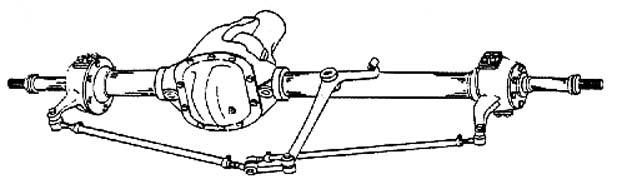
Short Style OEM Jeep Tie Rod Design
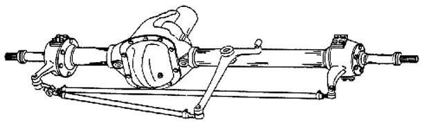
Long Style OEM Jeep Tie Rod Design
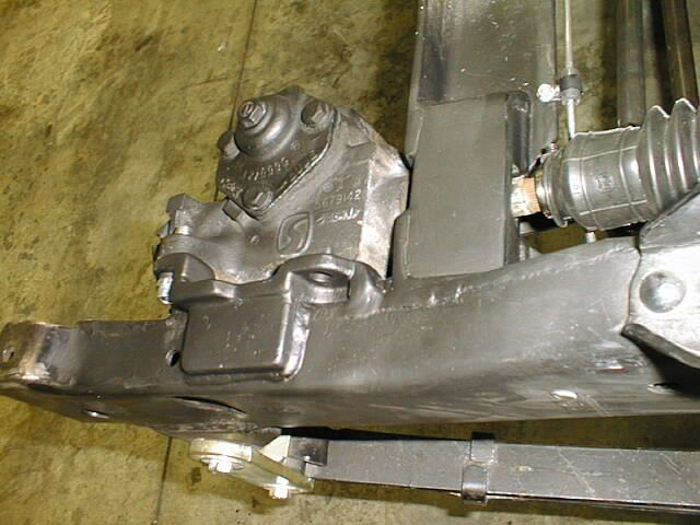
The Saginaw steering system requires the elimination of the stock gear box and bellcrank. The new steering box is mounted on the inside of the left front frame rail, just behind the bumper. Although this sounds simple, there are several things that must be considered before the installation can be completed. Such things include: Power or manual steering, Steering column type, Steering box location, Motor mount clearance on steering shaft, Tie rod size & length, Winch clearance.
On engine conversions that are retaining the original steering box location, you will be locating the engine position as close as possible to the original steering box. When eliminating the original steering box, you will be able to offset the new engine 1" towards the driver’s side in order to allow for additional front driveshaft and starter motor clearance. In 1971, Jeep changed their steering design to almost the exact same configuration as the kit that we offer. The difference between the original Jeep installation and our installation is mainly in the design of the mounting bracket for the steering box. Jeep also used a rag joint coupler between the steering box and driveshaft.
We offer a couple conversion kits. These kits are either power or manual steering conversions, and use either a Flaming River or Borgeson yoke design. None of these kits supply the steering box (manual or power), or steering pump and hoses (power applications). To help identify the kit necessary for your conversion, please consider the following information. Note: Full steering kits should not be ordered when converting Jeep Pickups & Wagons, since special tie rods will be required. 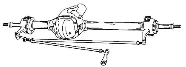
POWER & MANUAL STEERING BOX SELECTION:
Make sure the box that you select has the same basic configuration as the ones illustrated. Both Power & Manual boxes can be found in the 1960s and early 1970 GM cars, or Jeep vehicles 1972 & newer. The manual steering box must have a shaft stick out The Saginaw steering conversions for these vehicles is a proven advantage simply because they allow you to have better control of your vehicle both on and off the highway. The problem with stock steering on these vehicles is excessive play or backlash. In addition to offering a sound positive means of controlling your vehicle, it can be performed at a reasonable cost. Additional advantages include exhaust clearance, engine positioning, and custom steering columns. These kits fit Jeep vehicles only. Before you consider this conversion we recommend that you thoroughly read and understand the complete installation procedure. Do not take shortcuts on steering installations. We recommend that these conversions be installed by a qualified technician. The control of your vehicle depends on your steering performance. Failure of your steering system can result in severe damage and possible injury.
SAGINAW STEERING KITS:
Most Jeep vehicles had basically the same stock configuration. It is simply a gear box at the base of the steering column which controls a drag link towards the front of the vehicle. The bellcrank is mounted on the front crossmember or axle and uses a push-pull affect for steering. Because there are many motions and joints on this system, excessive free play and backlash develops. The Saginaw steering system requires the elimination of the stock gear box and bellcrank. The new steering box is mounted on the inside of the left front frame rail, just behind the bumper. Although this sounds simple, there are several things that must be considered before the installation can be completed. Such things include: length of approximately 3" long, and the spline on the shaft approximately 1" long.
The location of the Saginaw steering box will require a spud shaft. This shaft couples and extends the steering box shaft into the engine compartment. Both Power and Manual boxes have two spline sizes that mate to our spud shaft. Our manual steering kits are supplied with a .730” dia. 30 spline spud shaft. If your steering box has .730” dia. 36 spline, Part No. 716834-36 can be substituted. On power steering kits, we supply the most common spud shaft which is a .800” dia. 36 spline. On some of the newer Saginaw boxes, we have found them to have a .730” dia. 30 spline. Part No. 716834-30 can be substituted.
716834-30 - Spud shaft .730” dia. 30sp. female x 1” Double D Male (power & manual boxes)
716834-36 - Spud shaft .730” dia. 36sp. female x 1” Double D Male (manual boxes only)
716835 - Spud shaft .800” dia. 36sp. female* (power boxes) *716835 will be switching to 1” Double D Male in 2014.
BORGESON / FLAMING RIVER:
These kits are the newest and most recommended style that we manufacture. The steering shaft assembly connects directly to our steering spud shaft. This collapsible slip steering shaft extends to the firewall and can be adjusted to any length. With a 3/4" DD connection (round shaft having 2 flat surfaces), it is easily coupled to any of the yokes supplied in the kit or listed under the Custom Steering Column subheading. These kits require welding on the steering box mounting plate, frame enclosures, and firewall mounting plate.
716805 - Jeep conversion kit, Manual Saginaw box
716806 - Jeep conversion kit, Power Saginaw box (shown)
716806A - Jeep conversion kit, Power Saginaw box
(does not include column yoke and steering spud shaft.)
(These kits do not include boxes or pumps)
STEERING COLUMNS:
The stock steering column is the easiest option when installing the Saginaw steering. If you are planning to use a custom steering column, some fabrication will be necessary for mounting. The stock steering column protrudes through the firewall and into the engine compartment where it enters the stock Jeep worm gear steering mechanism. The steering box must be disassembled so that the worm portion of the steering column shaft can be cut off. Once removed, the end of the shaft must be machined to fit the universal joint provided. The diameter of this shaft must be machined to fit a 7/8" (.875") universal joint. After the shaft has been machined, the column can be reassembled with the modified shaft. To support the shaft in the center of the column, a bushing (716810) fits into the column housing with a precision fit on the shaft. Make sure the bushing and the shaft have sufficient clearance for easy turning. The column will then need to be assembled into the support plate. The new steering shaft bushing must be installed into the bottom of the steering column so that alignment and support of the shaft is maintained. With the bushing in place, you can now install the universal yoke. Slip the yoke in position onto the shaft and firmly up against the bushing. Before tightening the set screw, have someone push the steering wheel downward. You will find that the column has a slight spring tension. Make sure that the tension will provide a slight pressure of the universal yoke against the bushing. We require the universal yoke installation to have a spot drilled in line with the set screw. Failure to make each yoke installation as specified could result in the loss of control of the vehicle.
Borgeson / Flaming River: Using the one set screw provided on the U-joint, tighten it down to the shaft until a mark or indentation is made on the steering shaft. Remove the U-Joint and spot drill 3/16" deep where the set screw mark is indicated. Reinstall the U-joint and tighten the set screw until is comes to a stop. Next, using the opposite hole on the U-joint as a pilot hole, drill a 5/16" hole through the steering shaft & the opposite side of the U-joint. Using the shoulder bolt provided, install and tighten with the provided lock nut. All of these threaded areas should be secured using Loctite. Never weld on these steering U-Joint assemblies.
CUSTOM STEERING COLUMNS:
Custom columns offer several distinct advantages. The advantages include locks, tilts, flashers, and custom vehicle appearance. However, they do create some problems and require careful consideration when mounting them to the floorboard and universal joint connection.
Borgeson / Flaming River: Universal joints are available to match nearly every style steering column available. The special spline size on some of the custom columns will require a new U-joint. We offer a wide selection of various sizes. The new universal joint is supplied with a mating connection that will fit the new 3/4" DD steering shaft. If a custom column is being used and you have already purchased the stock Jeep 7/8" diameter column yoke, you will then need to exchange your universal joint for the one that will be required on your installation. We offer special yoke assemblies to connect a custom steering column to our Saginaw steering components.
716848 - 1" 48 spline Universal yoke (GM columns)
716849 - 1" DD x 3/4" DD Universal yoke (GM and Ford)
716850 - 3/4" x 36 spline Universal yoke (GM and Ford)
(The dimensions represent the column side of these yokes only. The opposite side of these yokes is a 3/4" DD)
STEERING SHAFT:
The control shaft between the end of the column and the steering box spud shaft is defined as the steering shaft.
Borgeson / Flaming River: With each kit, we have provided a 3/4" DD shaft that has a length of 36", and a special U-joint pre-assembled to the bottom of the shaft. The shaft can be shortened to the necessary length for your installation. The new shaft assembly has a 3/4" DD end that will need to fit into the steering column universal joint. Use the same procedure to spot drill both of the set screws, and Loctite the connections with the two lock nuts. The lower connection has been pre-assembled with a special 2" slip connector. The lower portion of this universal yoke is supplied with a 36 tooth fine spline connector that will fit directly onto the steering box (.730 x 36)or AA spud shaft. Always use Loctite on the double set screws and lock nuts for all universal yoke connections. A special boot has been provided that can be installed over the lower U-joint assembly. This special boot will provide a weather protective seal on the universal joint assembly. 716862
We have had request for steering shafts with different yoke ends, we now also offer a slip shaft without any yokes supplied. WE have also increased the selection of yokes that we carry. This will allow you to custom configure a steering shaft for your steering needs. Always use Loctite on the double set screws and lock nuts for all universal yoke connections. P/N 716863
716844 - Universal Joint 3/4"DD X .800 36 Spline 716843 - Universal Joint 1" DD X 7/8"
716847 - Jeep column shaft 3/4" DD x 7/8" 716845 - Universal Joint 1" DD X .3/4 - 36 Spline
716853 - Universal Joint 3/4" DD x 3/4" - 30 716846 - Universal Joint 1" DD X .800 36 Spline
716854 - Universal Joint 1" DD X 3/4" - 30
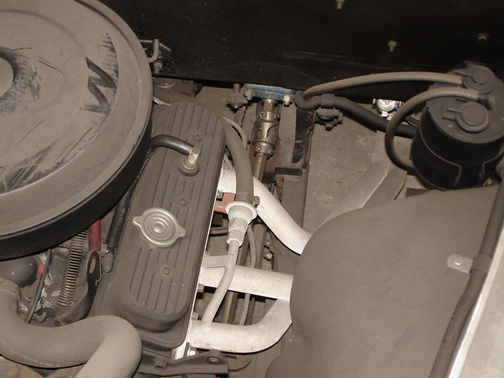
ROUTING THE STEERING SHAFT:
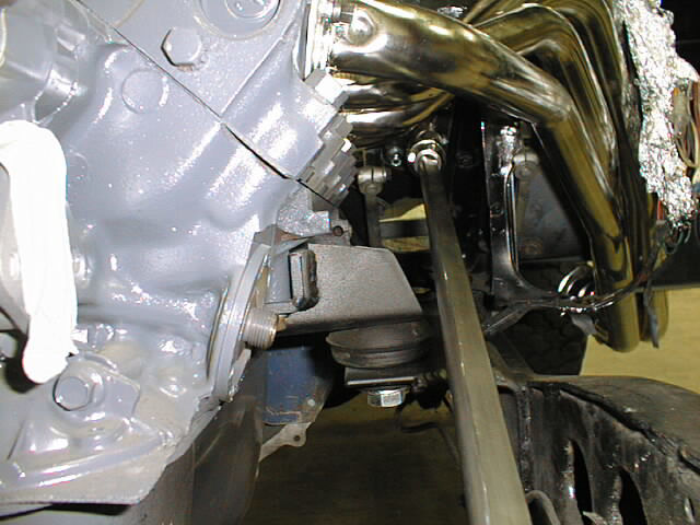
Routing the steering driveshaft may seem simple, but care should be taken as to the actual routing. On some Jeep installations, it may be necessary to go directly through the motor mount. Routes may be adjusted by changing the angle of the steering box slightly, or by extending the universal yoke from the column bushing with a spacer. Before any final route is decided, be sure to allow for suspension travel and engine movement. On some conversions, a third universal yoke might be considered along with a bearing pillow block.
Manifold clearance on Jeeps with a stock 225 V6. The steering shaft can have some exhaust clearance issues on some Jeeps. One that was brought to our attention is the Jeep 225 V6 with a Sawinaw steering swap. The steering shaft hits the stock manifold, two options for clearance would be switch to exhaust headers for the Jeep or switch to a Buick 231 1975 and newer rear wheel drive vehicle manifold.
FRONT CROSSMEMBER:
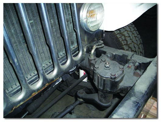
The early Jeeps used a bell crank mounted on the front crossmember, and this crossmember was originally located in the engine compartment. If an engine swap has been performed, we recommend installing a new crossmember located further forward, directly in line with the front grill. When installing the Saginaw conversion, this new crossmember will require an access hole that is roughly 2-1/2" in diameter to provide clearance for the steering spud shaft clamp. This access hole allows the steering spud shaft to extend through and into the engine compartment. In most cases, the front crossmember must be reinforced on both the top & bottom because of the diameter of the access hole.
STEERING BOX LOCATION:
The power steering box will require every bit of space between the bumper and front crossmember. It will usually require you to modify the lower flange of the front bumper by notching it for added clearance. The actual positioning of the steering box should be accomplished by bolting the box to the plate provided, and then temporarily clamping the plate and box to the inner frame rail until an ideal position is achieved. Make sure this position allows the steering spud shaft to extend through the front crossmember and into the engine compartment. Once in position, the plate must be completely welded to the frame. Since this plate encounters extreme forces from the steering system, the welding of this plate should be done by a certified welder. We have provided a pair of 3/16" thick steel frame enclosures to box in both of your frame rails, providing a good base for welding the steering box mounting plate. The steering box mounting plate must have a solid surface for welding and positioning. The extra plate is simply supplied for boxing of the passenger side frame rail. On vehicles equipped with winches, it may be necessary to offset the winch bumper to allow for the steering box clearance.
When using either of the two mounting plates, 716826 or 716838, you will be required to have these plates welded onto your frame rail. Both plates are made of steel so that a good weld can be made. These welds should be made only by a qualified welder. Do not short change your installation with a poor quality weld of these mounting plates to your frame rail. The plates should be welded along the complete perimeter. We have included a special frame-to-steering mounting plate gusset, 716832, to provide additional support from the outside of your frame rail to the bottom of the steering box mounting plate.
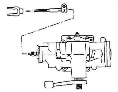
SAGINAW STEERING BOXES:
Power and Manual steering gear boxes are very similar. We have already illustrated what the two boxes should look like. Normal applications were on GM cars, but a few other vehicles are also using the same boxes. The steering box must be able to mount on the inside frame rail of your vehicle, with the input shaft extending horizontally toward the firewall. This input shaft is normally not long enough to extend fully into the engine compartment to couple with the steering driveshaft. This is why we offer steering spud shafts to extend these steering input shafts. On occasion, we carry power steering boxes which are listed at the end of the steering section.
Power: Not all power steering boxes are the same. Beginning in the late 1970s, three different power steering boxes have been produced. Before this, they were all externally the same. The major difference to be concerned with is the input shaft diameter. The most common style has a major diameter of .800" 36 spline, but we’ve also seen a .730 diameter 30 spline. A smaller input shaft is sometimes found on power steering boxes in light midsize cars, which is not compatible with the spud shafts produced by Advance Adapters.
On power steering boxes, you will be required to use four bolts when using our mounting plate, 716838. The 4 bolts must be installed from the bracket side into the steering box. Some of the newer Chevy boxes come only with a 3 bolt mounting flange. This is similar to the manual steering boxes. P/N 716838 will still work on these boxes. DO NOT drill out the threads in the power steering box assembly.
Manual: The manual boxes have variable input shaft lengths. The manual boxes that we recommend have an input shaft extending approximately three to four inches away from the main housing. The stock input shafts for these boxes can be found with a diameter of .730", and either 30 or 36 splines. The connection of this spud shaft to the input shaft is accomplished with a special clamp that locks these shafts together.
The manual steering boxes must be secured with a minimum of three socket head cap screws with high collar lock washers. The threads in the manual steering box must be drilled out for clearance of the 7/16" socket head cap screws so that the bolts can be installed through the steering box into the mounting plate.
TIE RODS:
Each of our kits include the necessary long & short tie rods for your conversion. The long tie rod connects the two front wheels, while the other connects the Pitman arm to the passenger side steering knuckle/center socket tie rod. Both tie rods are manufactured with both a right & left hand thread to assist in proper alignment. The Pitman arm that we have furnished with your kit has exactly the same taper that the Jeep tie rod ends have. Care should be taken for the proper fit of the tie rod end’s taper and threads when installing into the Pitman arm. In some cases, it may be necessary to use two or three washers on the top side of the Pitman Arm so that the threads on the tie rod end will secure the proper taper fit. All tie rod ends must be secured with a castle nut and cotter pin. All tie rod-to-tie rod end connections must have a tie rod clamp installed with a bolt, lock washer, and nut. We DO NOT find it acceptable to cut and weld the tie rods.
PITMAN ARMS:
The steering box Pitman arms vary from power to manual, and are not interchangeable. The Pitman arm supplied in each kit is for use on vehicles that are not equipped with a suspension lift. If your vehicle requires a dropped Pitman Arm, then we suggest that you contact a suspension lift company. We DO NOT find it acceptable to cut or bend our Pitman Arms.
POWER STEERING PUMPS:
There are only a few pumps available and most are interchangeable. We recommend the purchase of the power steering pump and steering box as a pair if possible. For proper installation, special hoses will probably have to be made. The hardware for mounting the pump to the engine can be standard parts from Chevy & Ford engines. Stock 4 & 6 cylinder applications require you to fabricate or modify existing standard brackets. On occasion, we carry power steering pumps which are listed at the end of the steering section.
TURNING ANGLE ADJUSTMENT:
To avoid damage to the outer axle U-joints, it is advisable that you check the turning angle. The following is a list of the correct turning angles.
CJ2A, CJ3A 23 Degrees CJ5 Up to Serial No. 57548-48284, 23 Degrees
CJ3B Up to Serial No. 57348-35326, 23 Degrees CJ5 After Serial No. 57548-48284, 27.5 Degrees CJ3B After Serial No. 57348-35326, 27.5 Degrees CJ6 Up to Serial No. 57748-12497, 23 Degrees
CJ6 After Serial No. 57748-12497, 27.5 Degrees
To adjust the turning angle stops, loosen the lock nut and turn the adjustment screw. On some early models, a secured weld will have to be broken. The adjusting screw is located on the axle tube near the knuckle housing. For further detailed information, refer to your vehicle service manual.
CASTER ADJUSTMENT:
The purpose of the caster adjustment is to provide steering stability, which will keep the front wheels in a straight ahead position. It also assists in straightening the wheels after making a turn. If the angle of the caster is found to be incorrect, correct it to the specifications given in your service manual. The correct angle is obtained by installing caster shims between the axle pad and the springs. If the camber and the toe-in are correct and it is known that the axle is not twisted, a check may be made by testing the vehicle on the road. Before road testing, make sure that the tires are properly inflated at the same pressure. If the vehicle turns easy to either side, but is hard to straighten out, insufficient caster for ease of handling is indicated. If correction is necessary, it can be accomplished by changing the shims between the spring and axle pads.
TOE-IN ADJUSTMENT:
Lift the front of the vehicle to raise the front tires off of the ground. Turn the wheels to the straight ahead position. Using a pencil or chalk, scribe a line in the center of each tire tread. The mark should circle the entire diameter of the tire. Measure the distance between the scribe lines at the front and rear of the wheels, using care that both measurements are made at an equal distance from the floor level. The distance between the lines should be greater at the rear then at the front by 3/64" to 3/32". To adjust, loosen the clamp bolts and turn the long tie rod with a small pipe wrench. The tie rod is threaded with right hand and left hand threads to provide equal adjustment at both wheels. Do not overlook the retightening of the two clamp bolts. It is a common practice to measure between the wheel rims. This is satisfactory providing the wheels run true. By scribing a line on the tire thread, a measurement is taken between the road contact points reducing error caused by wheel rim run out. It is recommended to have the alignment done by a qualified technician.
STEERING COMPONENTS:
Although we manufacture and sell complete kits for Saginaw steering conversions, we do offer the individual components.
716810 - Stock Jeep column bushing
716812 - Tie rod clamp
716814 - Spud shaft clamp
716816 - Manual pitman arm
716817 - Power pitman arm
716819 - Center socket tie rod end
716820 - Left hand thread tie rod end
716821 - Right hand thread tie rod end
716823 - Jeep column mounting plate
716824 - Jeep frame enclosures
716826 - Manual steering box mounting plate
716829 - Jeep tie rod 22-1/2"
716830 - Jeep tie rod 35-1/2"
(custom tie rods can be made for longer lengths)
716832 - Manual box mounting plate gusset
716834-30- Spud shaft .730” dia. x 30T (1” male DD)(manual & power)
716834-36 - Spud shaft .730” dia. x 36T (1” male DD)(manual)
716835 - Spud shaft .800” dia. x 36T (1” male DD late 2014)(power)
716841 - Universal Joint 1” DD x 1” DD
716845 - Universal Joint 1” DD x 3/4” - 36 Spline
716846 - Universal Joint 1" DD x .800 36 Spline
716847 - Jeep column shaft 7/8" x 3/4" DD
716848 - Universal Joint 3/4" x 1"-48 GM
716849 - Universal Joint 3/4" DD x 1" DD
SAGINAW POWER STEERING BOXES & PUMPS
Both Power & Manual boxes can be found in the 1960s & early 1970 GM cars or Jeep vehicles 1972 & newer. We also carry new power boxes & pumps which are as follows.
We stock Saginaw power steering boxes. These steering boxes are ideal for the offroad enthusiast that uses their vehicle as a daily driver. These units use a large piston and have a 16:1 turning ratio. The valving is designed for a more firm and precise steering effort. This gives you more stability and control at highway speeds, and less oversteer offroad. These units also help stabilize larger tires giving the vehicle a more stable feel on the highway. The PSC boxes are new and the Triton boxes are rebuilt.
716881-P - Saginaw power steering box with o-ring fittings
(.800 dia., 36 spline input shaft)
716882 - Triton Saginaw power steering box with o-ring fittings
(.730 dia., 30 spline input shaft)
We also offer a complement power steering pump. These pumps work well when combined with the steering boxes mentioned above. Larger cam packed with a larger rotor and vanes enables these pumps to flow 3.4 gallons per minute, and produce 1500 psi. The custom ported housing makes for less flow restriction, allowing the pump to run stronger and cooler.
716885-P - Power steering pump w/ o-ring fitting, (does not include pulley)
716886-P - Power steering pump w/ o-ring fitting and remote reservoir, (does not include pulley)
716887-P - Power steering pressure hose kit for o-ring box
716888-P - Power steering return hose kit for o-ring box
716889-P - Power steering heat sink cooler kit